

Manley Elop+ Stereo Limiter Compresor

*Cena sa popustom može da se ostvari ukoliko se plaća gotovinski, virmanom (preko računa) ili odmah debitnom karticom.
Garantujemo najnižu cenu!
- Svetogorska 9, Beograd
Manley ELOP®+ Electro-Optical Compressor Limiter
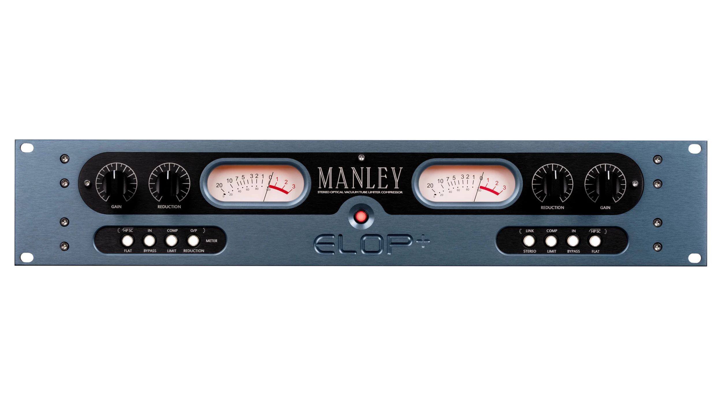
The Manley ELOP®+ represents a comprehensive re-engineering of the legendary ELOP Limiter, advancing the all-tube, electro-optical design with added versatility and performance. Hand-built in California, it employs light-dependent (optical) resistor technology with vacuum tube amplification throughout the signal path, to deliver musical, transparent and dynamic control for tracking and mixing sessions.
Tube Complement & Limiter Specifications
• 10:1 Limiter and 3:1 Compressor ratios
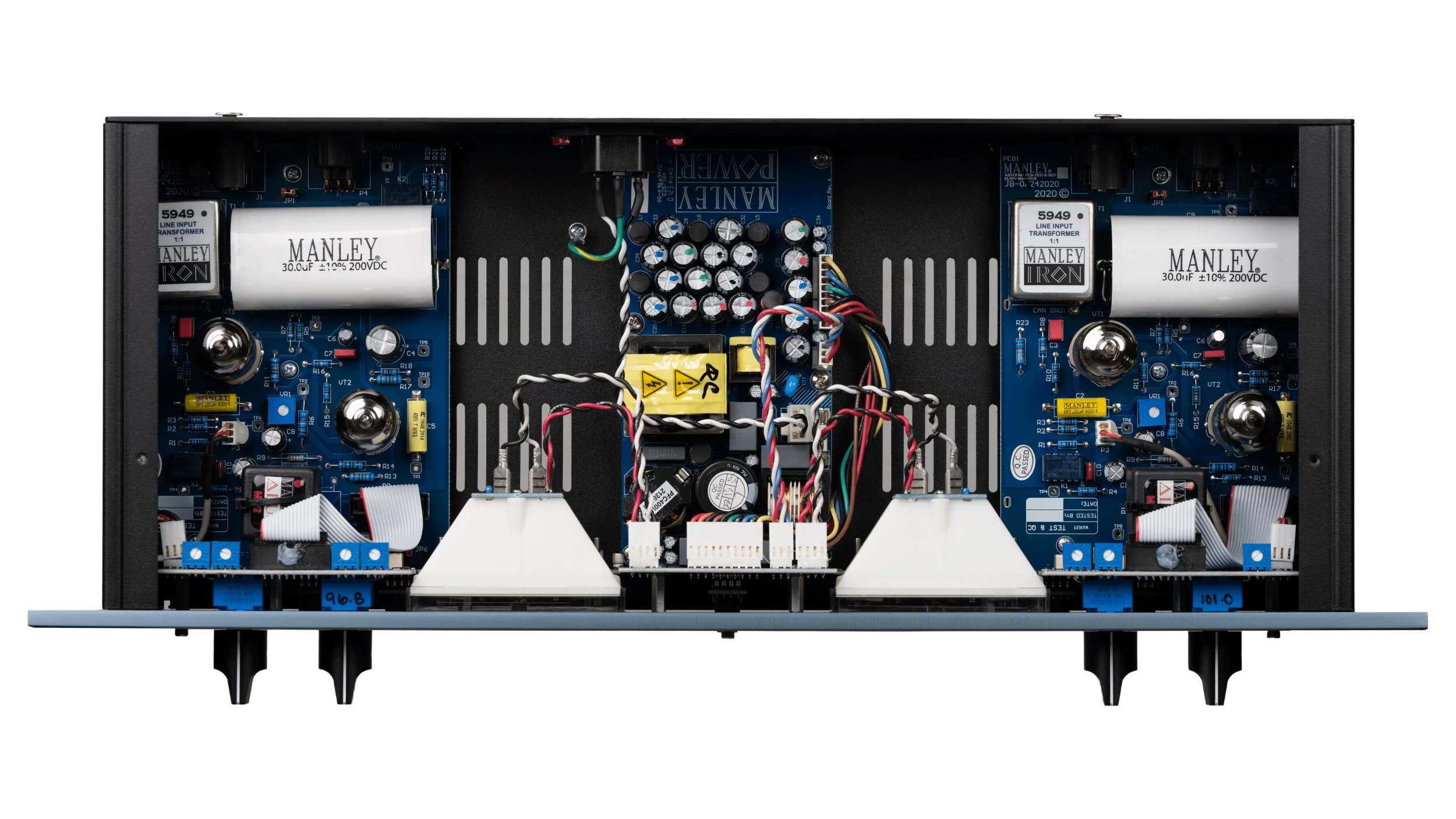
• All-tube audio path uses 5751 (gain) and 6922 (White Follower Output) dual triodes each channel
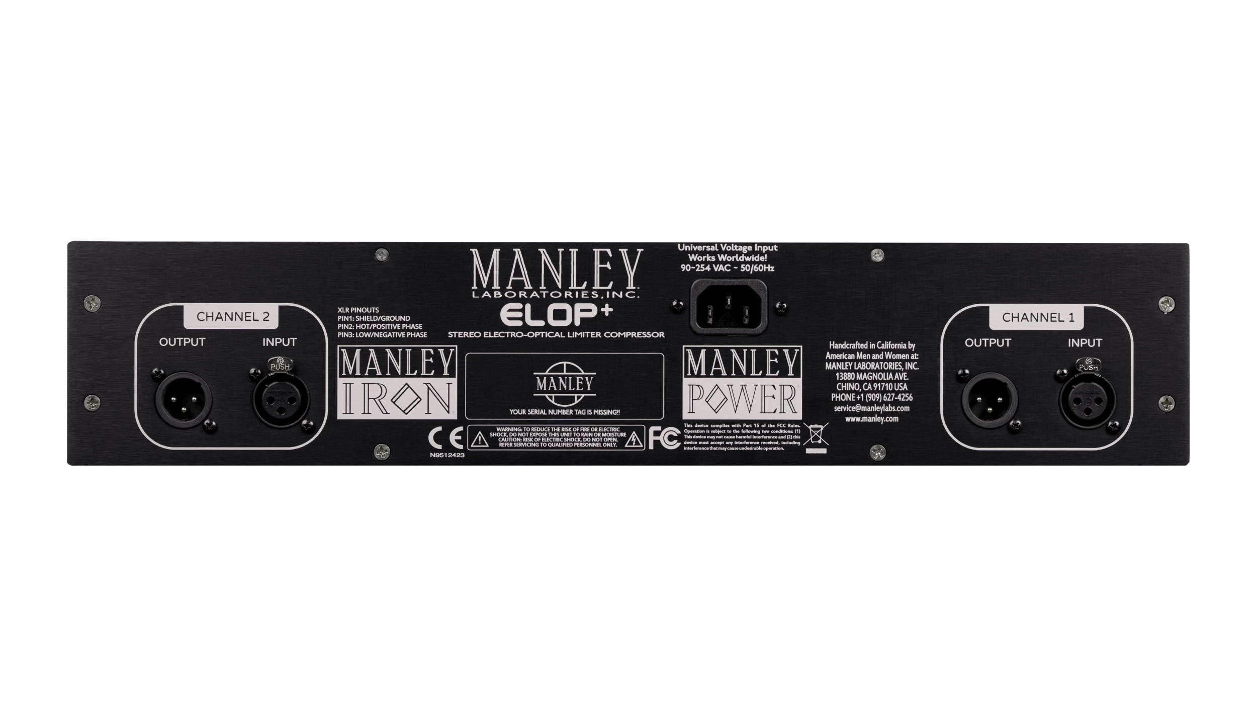
• Balanced Manley IRON® transformer-coupled XLR Inputs
• XLR impedance-balanced outputs
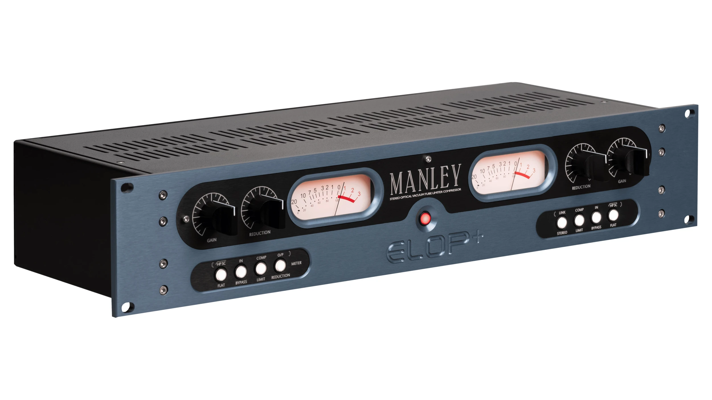
• BYPASS switches and AUTOMUTE with warm-up delay
• Large illuminated VU meters read Gain Reduction or Output levels
• STEREO LINK
• Side-Chain High-Pass Filter
• Standby Power Consumption: 0.5 Watts
• Universal internal power supply operates worldwide 90-250V~AC 50/60Hz
• ALL-TUBE audio path using a 5751 for gain, 6922 White Follower output tube (one each per channel)
• Silent Conductive Plastic GAIN control.
• Balanced MANLEY IRON Transformer coupled XLR input.
• Input impedance: 14 kOhms
• Maximum input level: +18dBu or 4.8V RMS @ 0.01% THD
• Hi-current White Follower Impedance Balanced XLR output.
• Output impedance=150 Ohms
• Maximum Output with 100 kOhm load= +30dBu @.009%THD+N, BW 22Hz-22Khz, 1Khz sine
• Maximum Output with 600 Ohm load= +20dBu @.015%THD+N, BW 22Hz-22Khz, 1Khz sine
• Output Headroom (Referenced to +4dBu)= 26dB
• Frequency Response= -0.15dB @ 10Hz, -0.1dB @ 20KHz
• Total Harmonic Distortion (1kHz sine @ +4dBu, BW 22Hz-22kHz) = 0.004 % THD+N
• Noise Floor Limiter Bypass= -90dBu (BW 22Hz-22kHz)
• Noise Floor Limiter Engaged= -88dBu (BW 22Hz-22kHz) Input set to Unity gain
• Dynamic Range= 118dB
• Signal to Noise Ratio = 92dB (Referenced to +4dBu)
• Bypass mode = Signal goes thru ALL-TUBE audio path (Bypasses limiter) this is not a “hardwire bypass”
• Unity Gain= Set Input Attenuator @ 1:00 o’clock
• Maximum Gain= 13 dB
• Common-Mode Rejection Ratio (CMRR)= 77dB (BW 22Hz-22Khz, +4dBu, 1Khz sine)
• Limiter Ratio= 10:1
• Compressor Ratio= 3:1
• Limiter: Attack= 15ms
• Limiter Release= 200ms
• Compressor: Attack= 75ms Release= 200ms
• Attack/Release times measured under following conditions: 4dB of Gain Reduction, 1kHz sine, +4dbu Input level, to 63% of total.
• Attack times are faster with higher input levels and heavier gain reduction. Typically for complete release, release times increases up to a couple of seconds, depending upon the amount of previous reduction.
• Maximum Limiting (with +4dBu 1Khz sine)= 12dB
• Maximum Compression (with +4dBu 1Khz sine)= 6dB
• Side-Chain High Pass Filter= 80Hz (Internal user adjust jumper to 150Hz)
• Automute warmup delay=30 seconds
• Operating mains voltage= 90 to 254 VAC (internal universal power supply)
• Mains voltage Frequency= 50-60 Hz
• Power consumption= 26 Watts
• Dimensions= (w,d,h) 19" x 7 x 3 1⁄2" (occupies 2u)
• Unit weight= 9.5 Ib
• Shipping weight= 10 Ib
Opis nije dostupan